Product Video
Product Specificatino
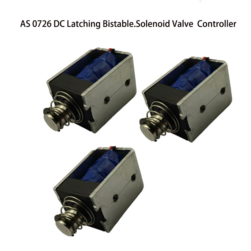
| Brand | AstSolenoid | Model Number | AS 0726 |
| Rated Voltage (V) | DC12V,18V or 24V | Rated Power(W) | 3.7 W |
| Work Model | Pull Push Type | Holding Force (N) | 4-13 N |
| Stroke(mm) | 3-8 MM Customized | Reset Time(s) | 0.2 |
| Service Life | 100 Thousand Times | Certification | CE,ROHS,ISO9001, |
| Material | Superior Magnet Iron | Lead Wire Length(mm) | 200 MM |
| Install Style | Screw | Tolerance of Dimension | +/- 0.1 MM |
| Water-proof | None | Insulation Class | B |
| Hi-Pot Test | AC 600V 50/60Hz 2s | Non-excitation Holding Force | 0 |
| Working Temperature | -10°C-100°C | Duty Cycle | 1-100% |
| Thread Depth(mm) | / | Payment Term | TT, or LC At Sight |
| Sample Order | Yes | Warranty | 1 Year |
| MOQ | 1000 pcs | Supply Ability | 5000 pcs per Week |
| Delivery Time | 30 Days | Port of Loading | shenzhen |
Product Detailed Description

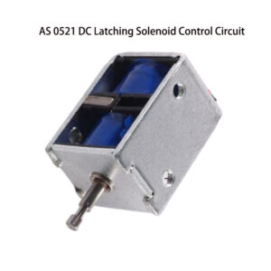
Key Design Considerations for Latching Solenoid Valves
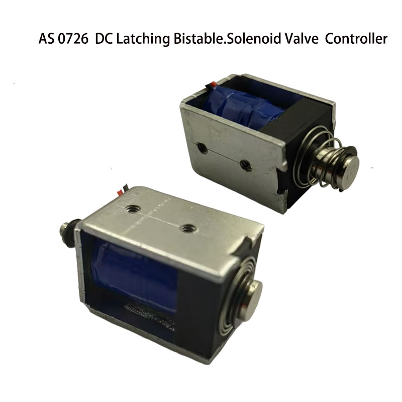
Latching solenoid valves always incorporate permanent magnets within their housings. When embarking on the design or development of a new latching solenoid, several critical factors demand careful consideration.
Pull Force in Power-Off State
The latching solenoid must still exert enough pull force to keep the plunger in place when power is cut.
Direction of Electric Current
The current’s direction dictates the magnetic polarity, which in turn controls whether the solenoid latches or releases the plunger.
Magnetic Holding Force
The permanent magnet generates the holding force, which keeps the plunger in contact with the fixed iron core when no electrical power is present.
Return Load and Electrical Power
Reliable switching and long-term performance hinge on considering both the mechanical return load and the available electrical power.
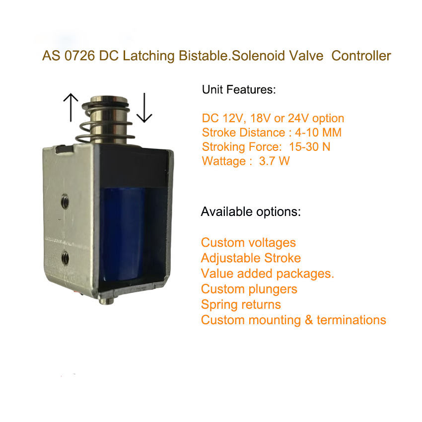
Unit Features
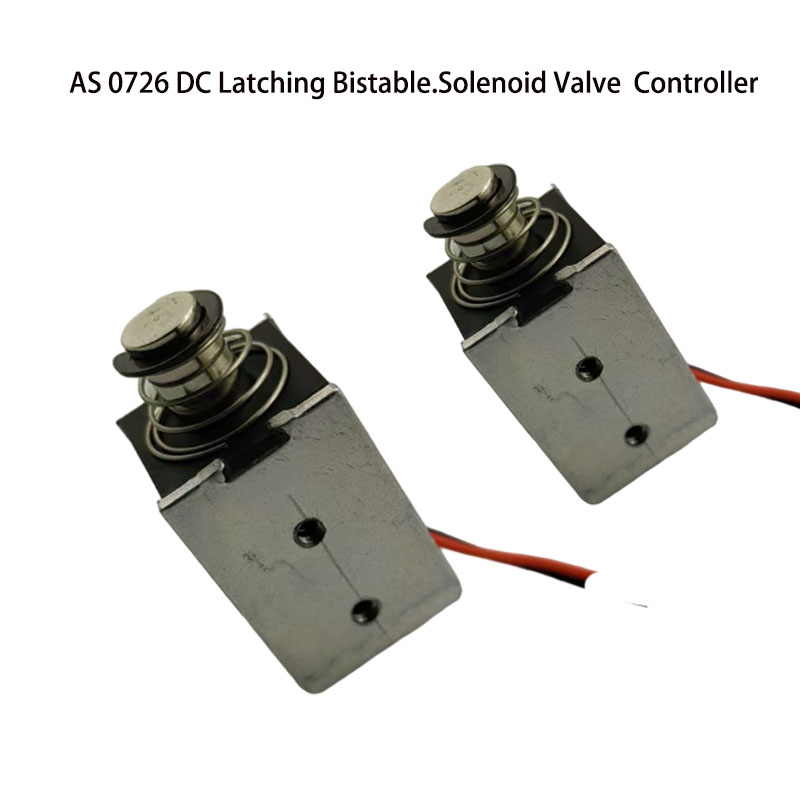
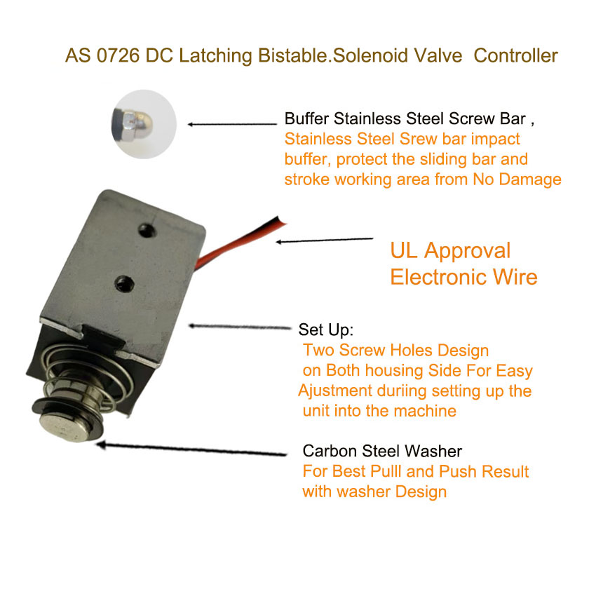
Housing:
Constructed from carbon steel, this housing features a zinc coating and a smooth surface, meeting RoHS standards.
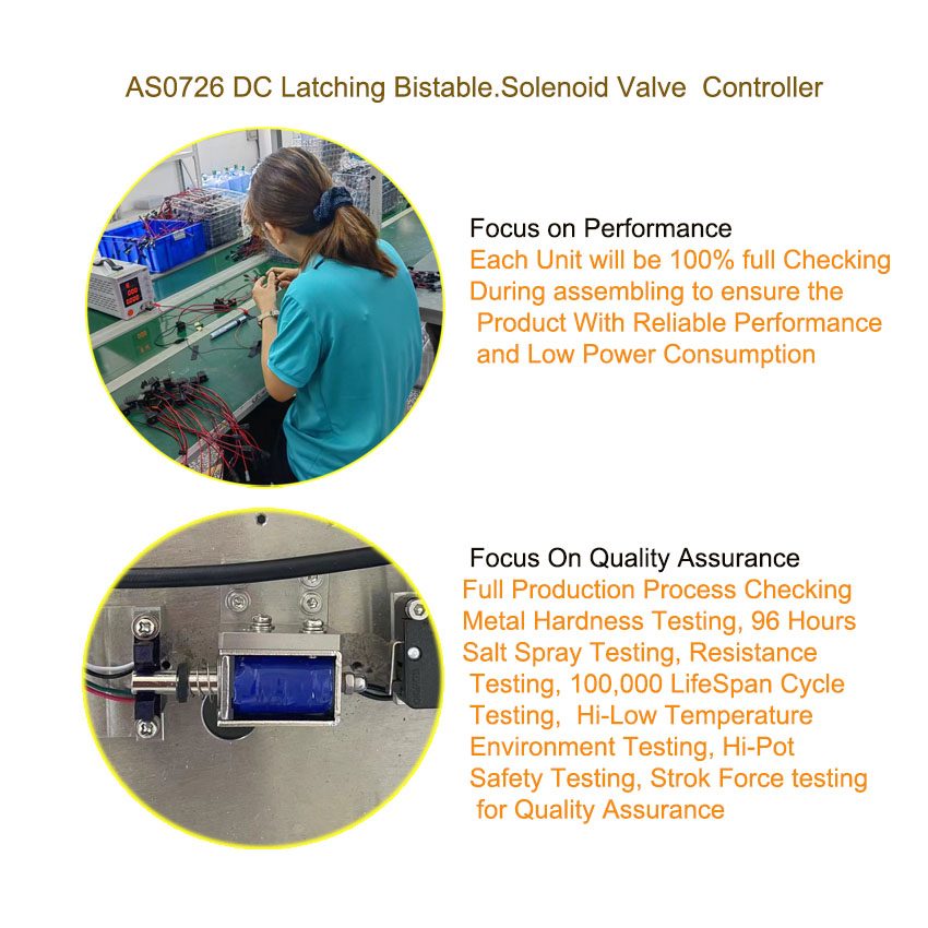
It successfully passed a 96-hour salt spray test, demonstrating its resistance to rust.
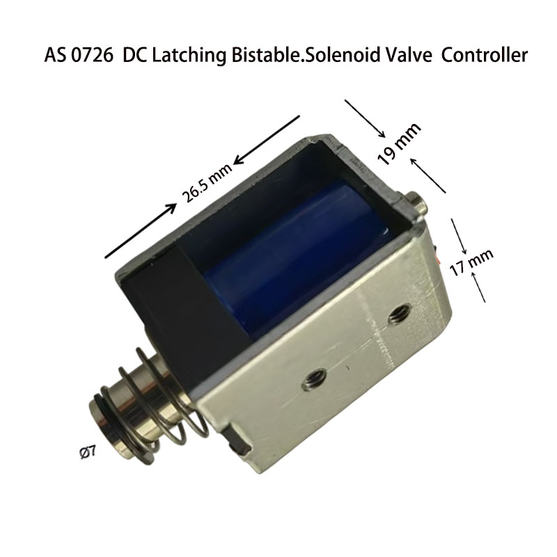
Plunger:
The plunger’s diameter ranges from 5 to 10 mm.
It’s made of carbon steel, also with a zinc coating and a smooth surface finish.
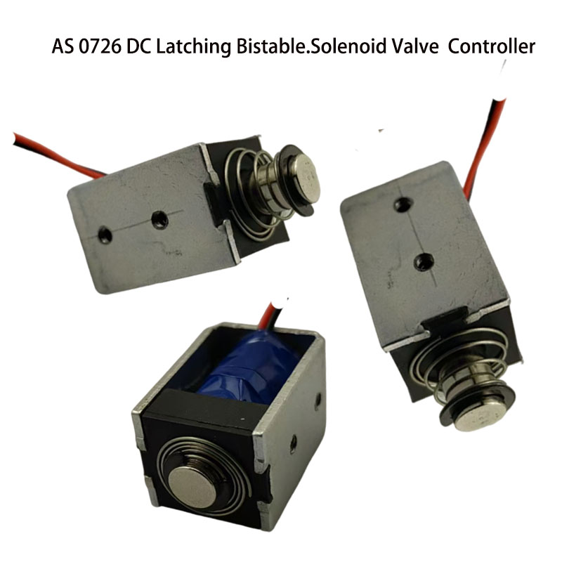
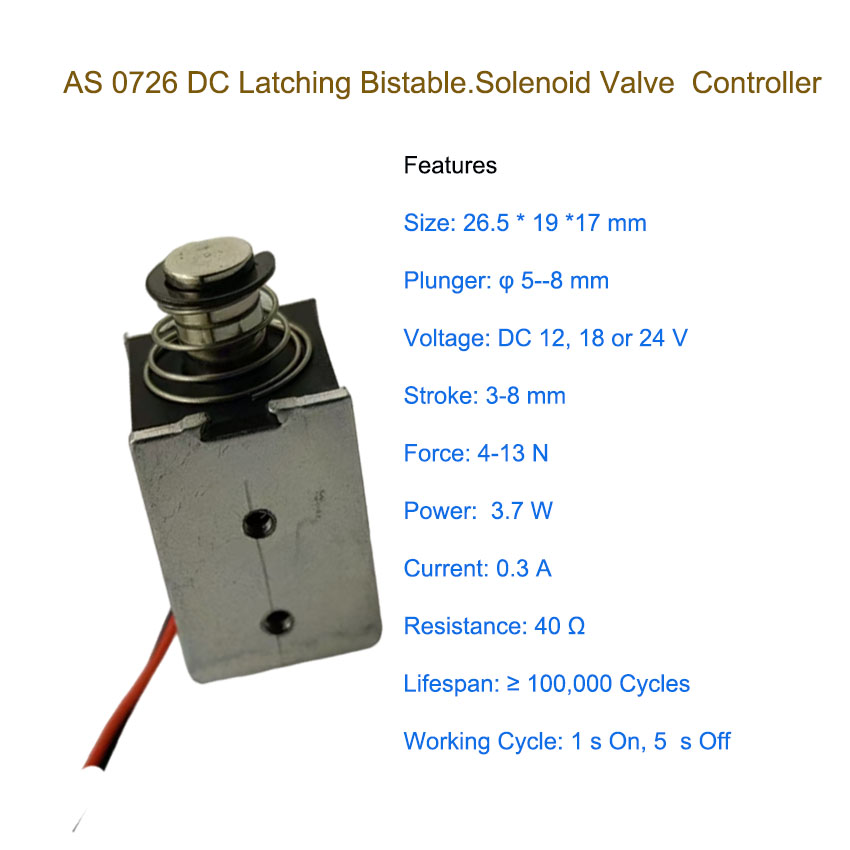
Stroke Range:
3 to 8 mm
Rated Power:
3.7 W
Holding Force:
4 to 11 N
Service Life:
Designed for up to 200,000 cycles.
Power Supply:
Compatible with DC 12 V, 18 V, or 24 V (optional).
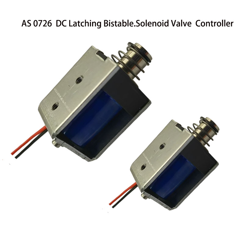
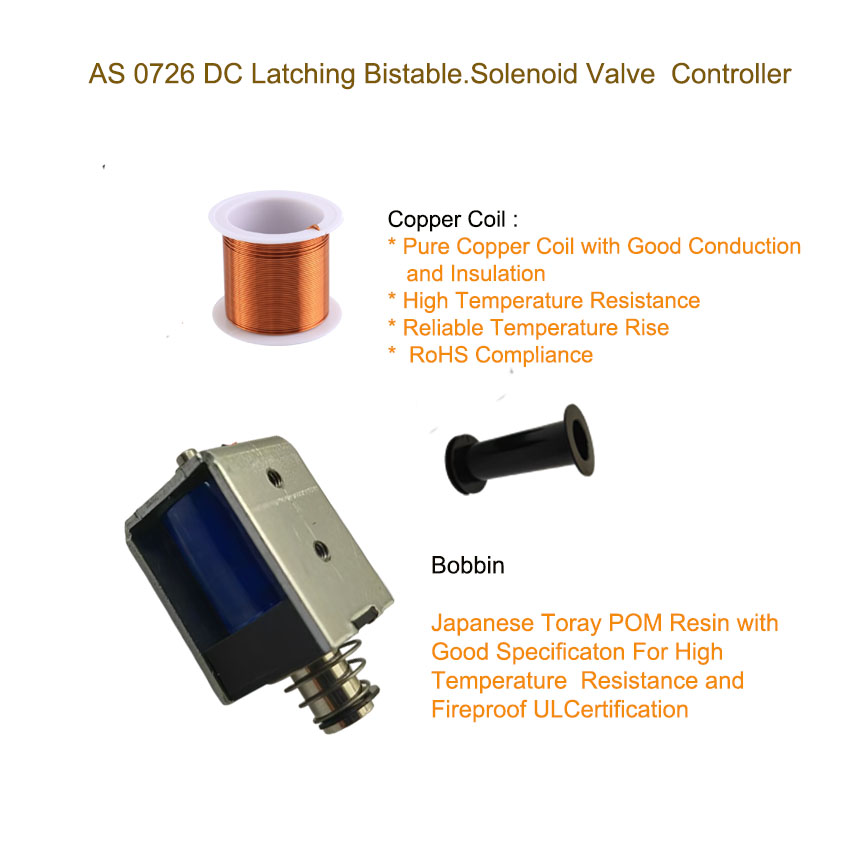
Copper Coil:
The winding is pure copper, ensuring stable and dependable temperature rise performance.
Insulation Class:
Class F (155 °C)
Duty Cycle:
1 second ON, followed by 5 seconds OFF.
Advantages of Latching Solenoids
Latching solenoids present several distinct benefits when compared to their non-latching counterparts.
Energy Efficiency
These solenoids draw power only when changing states – when they latch or release. This characteristic makes them particularly well-suited for devices powered by batteries or those where energy consumption is a critical concern.
High Reliability
The mechanical latching mechanism guarantees that the plunger stays put, even if power is interrupted or the system experiences a failure.
Compact Design
Latching solenoids are designed to be small and compact, which allows them to fit into applications where space is at a premium.
Customization Flexibility
These solenoids can be tailored to fit specific project needs, including voltage requirements, force, stroke length, mounting options, and the conditions under which they’ll operate.
Typical Applications of Latching Solenoids
Latching solenoids find applications in a broad range of sectors, such as:
Automotive
These devices are employed in door locks, seat-belt mechanisms, and fuel injector control systems.
Aerospace
They play a role in satellite antenna positioning, aircraft landing gear systems, and valve control units.
Medical Devices
Ventilators, infusion pumps, and surgical instruments that demand precise control and low power consumption also utilize latching solenoids.
Security Systems
Access control systems, electronic locks, safes, and security gates are other areas where they are commonly used.
Industrial Automation
Valve actuation, robotic grippers, conveyor systems, and automated control equipment also rely on these solenoids.
Frequently Asked Questions (FAQ)
1. What is a latching solenoid?
A latching solenoid is an electromagnetic actuator that uses a permanent magnet to hold the plunger in position after actuation. Electrical power is only required to change the state (latch or release), not to maintain it.
2. How does a latching solenoid differ from a traditional solenoid?
Traditional solenoids require continuous power to maintain the plunger position. In contrast, a latching solenoid maintains its position without power, resulting in lower energy consumption and reduced heat generation.
3. What happens when power is removed?
When power is removed, the plunger remains in its last position due to the magnetic holding force of the permanent magnet, ensuring reliable operation during power loss.
4. Why is current direction important in a latching solenoid?
The direction of the electrical current determines the magnetic polarity, which controls whether the solenoid will latch or release. Reversing the current direction switches the operating state.
5. What is magnetic holding force?
Magnetic holding force is the force generated by the permanent magnet that keeps the plunger firmly attached to the fixed iron core when no electrical power is applied.
6. How do I select the correct holding force?
The holding force should be selected based on:
-
External return load
-
Vibration or shock conditions
-
Safety margin required for the application
Our engineering team can help calculate the optimal holding force for your project.